

Perfect integration between control room and installed network of sound emitters. Modular, compact and versatile the TCS (Tyfon Control System) and TAS (Tyfon Alarm Station) are suited for a full range of applications. A scalable and flexible design,communication interfaces that fulfill the highest demands and a full range of proven integrated technology make the perfect combination between human behavior and alarm signals. Communication between TCS and TAS is made by Modbus RTU protocol and the medium can be radio, serial cable or Ethernet (Copper, Fiber or Wireless). TCS and TAS are mounted in steel cabinets and each cabinet is equipped with batteries and battery charger. Mains supply cable is laid through a gland at cabinet bottom. The radio antenna is mounted on the topside of cabinet. Installations with far distance between TCS and TAS outdoor antennas are needed.
Function description of TYFON control
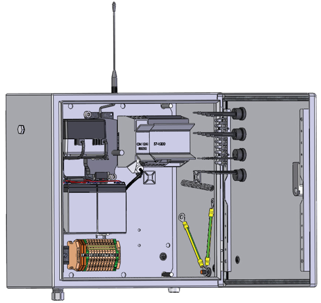
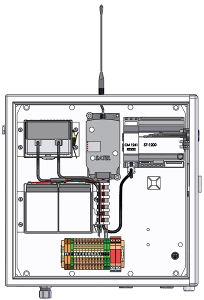
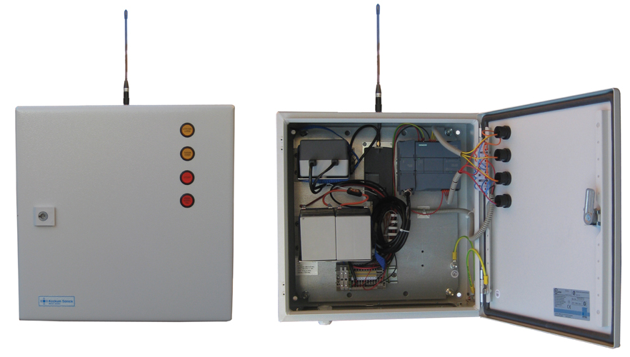
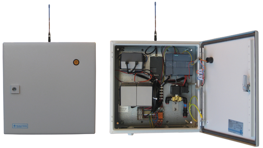
Overview TCS
The TCS has buttons for activating alarms on the remote TAS that are included in the system. On the front door are push buttons for each alarm signal that can be activated and one stop button. Status indicator shows with a code sequence i.e. bad communication to any TAS.
Push button 1 activates alarm signal 1. The push button needs to be pressed min 1 sec for it to activate. When it activates, the indicator in the push button goes yellow.
Push button 2 activates alarm signal 2. The push button needs to be pressed min 1 sec for it to activate. When it activates, the indicator in the push button goes yellow.
Push button 3 stops ongoing alarm signal and light indicator in the push button goes red.
The red fault indicator shows a serial of long and short flashes to indicate communication faults and TAS deactivation. The TCS will poll all the TAS every 15th second. It will check communication status and if the stations are deactivated/ activated.
Communication error
Communication error is displayed with 2 long flashes and the short flashes for TAS id.
Example 1: ____ ____ __ __ 2 long, 2 short = TAS 2 communication error
Example 2: ____ ____ __ (pause) ____ __ __ 2 long, 1 short, pause, 1 long, 2 short = TAS 1 communication error and TAS 2 deactivated
Deactivated TAS
A deactivated TAS is shown by the sequence of one long and one to configured amount of TAS short flashes. The long flash is 2 seconds on and 1 second off. The short flash is half a second on and half a second off. The sequence is repeated after 3 seconds.
Example 1: ____ __ __ 2 long, 2 short = TAS 2 communication error
Example 2: ____ __ (pause) ____ __ __ __ 1 long, 1 short, pause, 1 long, 3 short = TAS 1 and 3 deactivated
Configuration of TCS is done by connecting a computer to the PLC. A configuration program is supplied where the parameter for number of TAS can be entered. Counters for amount of polling requests of TAS, alarm activation messages and error in communication can be checked and reset from the configuration program too.
Overview TAS
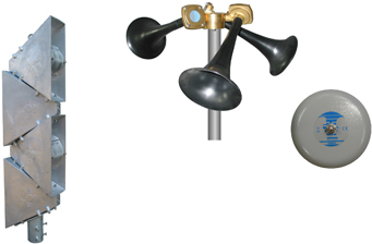
TAS to be configured in combination with bells, air horns or electro acoustic sound emitters. The TAS has 1 push button for deactivation/activation and 2 relay outputs for alarm signals.
Push button 1 pressed for 1 second will deactivate the alarm station for one hour. The lamp on button 1 will be on when the station is deactivated. If there is an ongoing alarm, the outputs will be deactivated. If there is sent out an alarm, the alarm will not be sound in the deactivated station.
Push button 1 pressed for 5 seconds will reactivate the station. The lamp on button 1 will be off when the station is reactivated.
Configuration of TAS is done by connection a computer to the PLC. A configuration program is supplied where the parameters for TAS id and some parameters for signal characteristics can be entered.